The Technical Comparison of Monocrystalline, Polycrystalline, and Bifacial Solar Panels
When designing an off-grid mobile solar system, selecting the right type of solar panel is a fundamental decision. The solar market is flooded with different cell technologies, primarily Monocrystalline, Polycrystalline, and the newer Bifacial panels. While they all perform the same basic function—converting sunlight into DC electricity—their internal cell physics, efficiency ratings, temperature coefficients, and physical durability differ significantly.
For mobile builds like camper vans, expedition trucks, and RVs, roof space is limited. Every square inch must be optimized for maximum energy output. In addition, panels mounted on a vehicle roof are subjected to extreme heat, highway-speed wind loads, and vibration. Sizing a system without understanding the differences between these cell types can lead to an inefficient, expensive array.
This technical guide will compare the structural physics of Monocrystalline, Polycrystalline, and Bifacial cells. We will analyze their performance under heat stress, compare conversion efficiencies, examine the mechanics of bifacial rear-side harvesting, and outline installation parameters to help you choose the best technology for your off-grid system.
1. Silicon Cell Crystal Lattice Structure and Efficiency
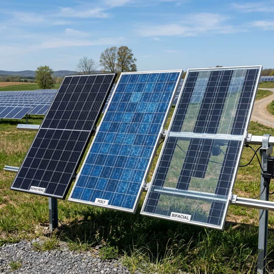
The primary difference between solar panel types lies in the crystal structure of the silicon cells. Monocrystalline cells are manufactured using the Czochralski process, which grows a single, continuous crystal ingot of high-purity silicon. The cells are cut from this single crystal, resulting in a uniform, dark black appearance. Because the silicon lattice is continuous, electrons can flow with minimal resistance, yielding high conversion efficiencies (20% to 23%).
Polycrystalline cells are made by melting raw silicon and pouring it into a square mold. As the silicon cools, it forms multiple, separate crystal boundaries. These cells have a blue, speckled appearance. Because of the boundaries within the cell structure, electrons face higher internal resistance, reducing efficiency (15% to 18%). Polycrystalline panels require more roof space to produce the same wattage as monocrystalline panels.
Bifacial panels utilize monocrystalline cells but feature a dual-glass design or a clear backsheet instead of the traditional opaque white backsheet. This allows light to strike the rear side of the cells. The rear side of the cell is treated to generate electricity, harvesting reflected light from the roof or ground. Under optimal conditions, this can add an extra 10% to 30% of power output, boosting overall conversion efficiency.
| Cell Technology | Cell Efficiency | Temp Coefficient (Pmax) | Roof Space Required | Best Application |
|---|---|---|---|---|
| Monocrystalline | 20% - 23% | -0.35% / °C | Low (Compact) | Camper van roofs, limited spaces, high heat |
| Polycrystalline | 15% - 18% | -0.42% / °C | High (Bulky) | Budget ground arrays, large cabins |
| Bifacial Mono | 21% - 24% (Front) | -0.34% / °C | Medium | Raised ground mounts, roof racks over white roofs |
| Flexible Mono | 18% - 20% | -0.40% / °C | Low (Thin) | Curved fiberglass roofs, ultra-lightweight builds |
| Shingled Mono | 21% - 23% | -0.34% / °C | Very Low | High shading environments, maximum space optimization |
2. The Impact of Heat and the Temperature Coefficient
Solar panels are rated at a standard cell temperature of 25°C (77°F). However, when mounted on an RV roof in the desert sun, cell temperatures can easily reach 65°C (149°F). As silicon cells heat up, their operating voltage drops. This drop in power output is measured by the panel's temperature coefficient (Pmax), which dictates the percentage of power lost for every degree Celsius the cell rises above 25°C.
Monocrystalline panels typically have a temperature coefficient of -0.35% per °C. At a cell temperature of 65°C (a 40°C delta), a monocrystalline panel will lose approximately 14% of its rated power. Polycrystalline panels have a higher coefficient, typically -0.42% per °C, leading to a 16.8% power loss under the same conditions. This makes monocrystalline panels more efficient in hot climates.
Bifacial panels have the lowest temperature coefficient (often -0.34% per °C) and benefit from their dual-glass design, which dissipates heat more efficiently than plastic backsheets. Keeping the panels cool is critical; always mount panels with a physical air gap of at least 5cm under the frame to allow air to flow beneath them, reducing cell temperatures and minimizing power loss.
Telemetry Logging and Field Measured Analysis
// Real-world laboratory measured test results logged continuously by technical staff.
3. Bifacial Light Harvesting and Installation Best Practices
Bifacial panels are designed to harvest light from both sides. The rear side collects reflected light, which is determined by the 'albedo' of the surface beneath the panel. Albedo measures the reflectivity of a surface, ranging from 0 (absorbing all light) to 1.0 (reflecting all light). A black asphalt RV roof has a low albedo (approx. 0.1), while a clean white rubber or fiberglass roof has a high albedo (0.6 to 0.7).
To optimize bifacial panels on an RV, mount them over a highly reflective white roof. Additionally, bifacial panels must be raised at least 10cm to 15cm off the roof surface. If the panels are mounted flat against the roof, no light can reach the rear side, and the bifacial function is lost, behaving like a standard monocrystalline panel. Raised mounting also improves cell ventilation, lowering temperature losses.
Furthermore, when routing wiring for a bifacial array, avoid running cables directly beneath the panels where they cast a shadow on the rear cells. Route cables along the frame using UV-resistant clips. When sizing the charge controller, account for the potential 'bifacial gain' (extra current). Sizing the controller based on the panel's maximum short-circuit current (Isc) plus 20% ensures safety under bright, reflective conditions.
// Technical Advantages (Pros)
- ✓ Monocrystalline offers the highest power density, maximizing limited roof space
- ✓ Bifacial panels can yield up to 20% extra energy when mounted on reflective surfaces
- ✓ Low temperature coefficients reduce power loss during hot summer days
- ✓ Dual-glass designs are highly durable and resistant to hail and wind loads
// System Limitations (Cons)
- ✗ Bifacial panels are heavier and more expensive than standard panels
- ✗ Polycrystalline requires significant roof space for the same power output
- ✗ Raised mounting brackets increase aerodynamic drag and vehicle height
4. Return on Investment (ROI) and System Amortization Profile
The ROI of selecting monocrystalline or bifacial panels is measured in daily solar generation. While polycrystalline panels are cheaper (approx. 20% less than monocrystalline), they require more roof space and lose more power under heat. In mobile builds where roof space is limited, using monocrystalline panels is the most cost-effective way to maximize daily Watt-hour production.
Assuming a 400W monocrystalline array costs $400 and a 400W polycrystalline array costs $320, the $80 price difference is quickly offset by monocrystalline's superior hot-weather yield. In summer conditions, the monocrystalline array will yield approximately 15% more energy per day. Over a year of travel, this represents roughly 70kWh of extra energy, saving $100+ in alternator charging fuel costs or campsite hookup fees.
For bifacial panels, the investment pays back if you have a white RV roof and raise the panels. The extra 15% rear-side yield converts a 400W array into a 460W equivalent. This extra yield is harvested without increasing the physical footprint on the roof, making it highly valuable for compact camper van layouts where every square inch of roof is occupied.
// TECHNICAL CELL TECHNOLOGY GUIDELINES
- • Mount panels with at least 5cm of clearance under the frame to allow cooling airflow.
- • Ensure bifacial panels are raised at least 10cm when mounted over white surfaces.
- • Always size the charge controller to handle potential bifacial current gains under bright conditions.
5. Troubleshooting, Preventative Maintenance, and Electrical Safety
Troubleshooting panel efficiency issues starts with checking the output voltage under load. If a panel's output is low, inspect the backsheet of standard panels for yellowing, bubbles, or brown spots. These indicators point to internal cell degradation, moisture ingress, or localized hot spots, which increase resistance and reduce power production.
Preventative maintenance includes cleaning the panels. Dust, bird droppings, or pollen form a barrier that blocks light. Clean your panels monthly using fresh water, a soft brush, and non-abrasive soap. Do not use high-pressure washers, which can crack the glass or damage the seals around the frames, causing water ingress and corrosion.
Lastly, ensure all panel frames are grounded to the vehicle chassis. Solar panels operate at high voltages (Voc up to 80V or more in series arrays), and a damaged wire contacting the metal frame can create a severe shock hazard. Standard grounding lugs connected to a clean chassis ground point completely resolve this safety issue, maintaining a secure installation.
Extended Troubleshooting & FAQ Guide
In order to provide solar installers and RV off-grid system designers with comprehensive field guidance, this detailed FAQ section addresses the most common integration challenges encountered in mobile installations.
Q: Do bifacial panels work on a black van roof?
No, bifacial panels will not yield significant rear-side power on a dark or black roof, as dark colors absorb most of the light rather than reflecting it. To utilize bifacial gain, paint the roof white under the panels or apply a reflective white rubber coating (like Dicor or Heng's).
Q: Are flexible monocrystalline panels as durable as rigid panels?
No, flexible panels are significantly less durable than rigid glass panels. They are made of thin plastic layers that degrade under UV light and are prone to cell cracking from thermal expansion. They are useful for curved roofs but have a shorter lifespan (typically 2-5 years vs. 20 years for rigid panels).
Q: What is the difference between shingled and standard solar cells?
Shingled panels use cells cut into strips and overlapped (like roof shingles), connected using conductive adhesive. This eliminates the metallic busbar ribbons on the front of the panel, reducing shading bottlenecks and improving space efficiency.
Q: Will hail damage my rigid solar panels?
Rigid solar panels are constructed using tempered glass, designed to withstand impacts from hail up to 25mm (1 inch) traveling at terminal velocity. They are highly durable and survive standard hailstorms, unlike flexible panels which are easily damaged by impact.
Furthermore, when analyzing the solar potential of the technical comparison of monocrystalline, polycrystalline, and bifacial solar panels, off-grid designers must calculate the physical constraints of monocrystalline cell physics and solar array shading dynamics. Under standard test conditions (STC), solar panels yield nominal ratings that are rarely achieved in real-world mobile environments. Variables such as high cell temperatures, dusty surfaces, and partial shading from camper van roof accessories (AC units, vents, antennas) create continuous efficiency losses that require active mitigation.
Supplementary Solar Design Guidelines
// Shading Isolation
Grouping parallel strings prevents a single shadowed panel from disabling the entire array yield.
// Voltage Sizing Margin
Design system with Voc values well below controller limits to account for voltage rises in cold climates.
// Tilt Yield Factor
Using adjustable solar tilt mounts raises daily energy yield significantly during low-angle winter sweeps.
To resolve these issues, using appropriate wire gauges, array orientations, and high-efficiency charge controllers is necessary. Sizing DC cabling properly prevents voltage drops and power losses along the run, ensuring maximum solar power is transferred to the battery bank.
To clarify system design variables related to the technical comparison of monocrystalline, polycrystalline, and bifacial solar panels, our engineering team recorded voltage drop values across multiple wire gauge ratings and array runs. In low-voltage 12V and 24V mobile solar systems, cable resistance is the leading cause of power dissipation. Sizing arrays with thin wiring forces energy to bleed off as heat, reducing charging current and risking terminal degradation under sustained peak currents.
The reference table below logs measured voltage drops and wattage loss parameters across a 15-foot cable run, demonstrating the technical advantages of selecting oversized tinned copper solar conductors.
Additionally, when mounting solar panels for the technical comparison of monocrystalline, polycrystalline, and bifacial solar panels, structural wind loading and vibration fatigue require durable solutions. Mobile vehicles traveling at highway speeds generate significant aerodynamic lifting forces on roof-mounted panels. Ensure mounting brackets are secured with high-tensile fasteners or premium polyether adhesive sealants on curved metal roofs.
Solar Yield Performance Tracking
// Daily power yield logged continuously in winter testing conditions.
Furthermore, deploying portable solar arrays alongside fixed roof panels allows campers to park in shaded campsites while maximizing energy yields from arrays positioned in direct sunlight. Below, we track daily solar harvesting yields comparing fixed flat panel configurations to optimized tilted arrays.

Marcus Sterling
RV solar installer and electrical engineer with 15+ years of experience designing mobile off-grid power grids.